Install Libreboot Open BIOS on Sony PlayStation (PS1/PSX)
The PlayStation is a computer like any other. It ought to run all Free Software if you want it to, and you can! In this document, you will learn how to replace the Sony BIOS on your PlayStation, with a fully Open Source one instead.

| Specifications | |
|---|---|
| Manufacturer | Sony Computer Entertainment Inc. |
| Name | PlayStation |
| Variants | PlayStation, PSOne, Net Yaroze |
| Released | 1994 (Japan), 1995 (Worldwide) |
| CPU | MIPS R3000 @ 33.8688 MHz |
| Graphics | Custom 3D processor by Toshiba, 1MB Video RAM |
| Sound | 16-bit custom Sony SPU |
| I/O | CD-ROM, analog Audio/Video, Serial, Parallel |
| Memory | 2MB EDO DRAM |
| Architecture | MIPS I instruction set (RISC) |
| Original boot firmware | Sony PS1 BIOS (USA/JPN/EU) |
| Flash chip | 512KB Mask ROM |
Open source playstation (PS1/PSX) BIOS
This uses the free/opensource BIOS developed by the PCSX-Redux team, which you can learn more about here:
https://github.com/grumpycoders/pcsx-redux/tree/main/src/mips/openbios
Download pre-built BIOS
Get it here:
https://www.mirrorservice.org/sites/libreboot.org/release/stable/20241206/roms/playstation/
Other mirrors are available, at the Canoeboot download page; look in the roms/playstation/ directory for a given Libreboot release. This is built from the available sources in Libreboot releases, based on the information written below.
You can use this in a PlayStation emulator or on real hardware - the rest of this page will tell you how to use it.
Build from source
OPTIONAL: You could alternatively use the pre-built version (see above).
First, please make sure you have build dependencies. The build logic in lbmk has been tested on Debian 12 (x86_64) and you can do this for example, as root:
./mk dependencies debianThe arch and dependencies should also work nicely, if you want to replace debian with one of those in the above example; you need to get the cross compiler (mipsel one) from the AUR, which you will see when running e.g.:
./mk dependencies archIf you have another distro, or you’re unsure, the PCSX-Redux project also provide generic instructions for other distros. Please see:
https://github.com/grumpycoders/pcsx-redux/blob/main/src/mips/psyqo/GETTING_STARTED.md
When you have the dependencies, including mipsel cross toolchain, you can just do this in lbmk:
./mk -b pcsx-reduxThis commonly only builds the BIOS part. If you want to build all of PCSX-Redux, you can, but lbmk does not provide automation for this.
Installation
If all went well, you should see openbios.bin located under the bin/playstation/ (within lbmk). Alternatively, you may be using a release after Libreboot 20240612 that has it pre-built. Either way is fine.
The openbios.bin file is your new BIOS build.
Emulators
Most PlayStation emulators rely on low-level emulation to execute the real BIOS. The Open BIOS by PCSX-Redux (as distributed by Libreboot) can also be used, and boots many commercial games, plus homebrew.
These emulators can boot many commercial games, with varying degrees of compatibility, and they can also boot any homebrew/opensource games that you might develop yourself, or that others have written.
Simply load your openbios.bin file into the emulator, using the instructions provided with your chosen PlayStation emulator. You can even freely redistribute this BIOS, because it’s free software (released under MIT license), which is a major advantage over Sony’s original BIOS.
Hardware
OpenBIOS has been tested on official hardware by third party users, but it comes with some caveats.
Limitations
Please read this before flashing your PS1 with OpenBIOS, as OpenBIOS removes some functionality from your PS1. From reading the documentation, it seems that OpenBIOS is essentially a very well-engineered proof of concept that happens to boot a majority of games; some polishing is still needed to make this useful on a real machine.
With OpenBIOS Flashed, you will lose the following functionality - Open BIOS does not seem to implement a memory card save handler at present; you can save and load games, in-game, but there is no built-in program for copying and deleting saves between memory cards. - You do not get to listen to music CDs. - Not all games will boot under OpenBIOS. For a list of games, see Game compatibility below.
The main usefulness of the Open BIOS is that it’s under an MIT license, and therefore legal to distribute; anyone wishing to use an emulator can use a compiled copy of the Open BIOS, and distribute it freely without trouble.
Replacing the PS1 BIOS
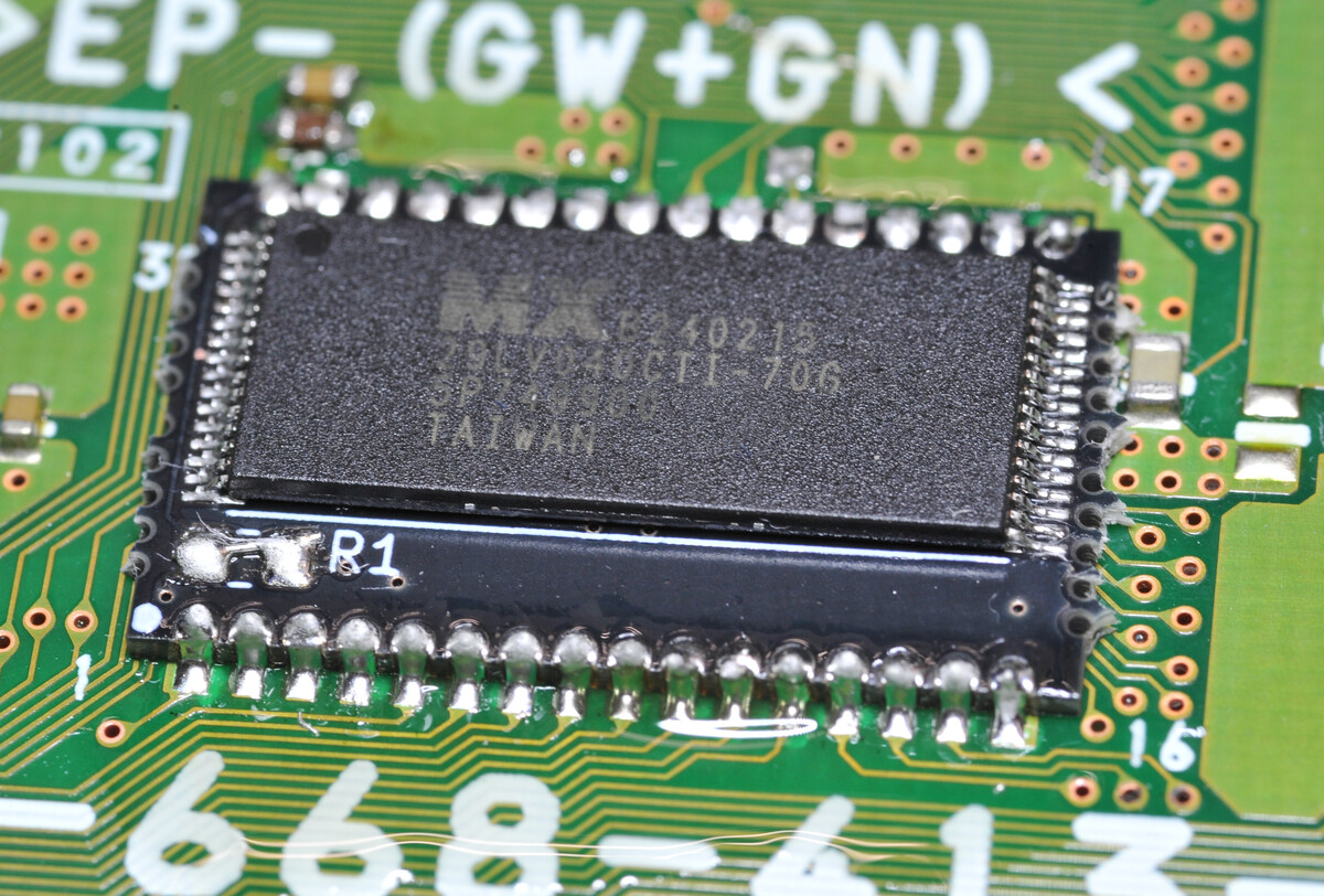
The PS1 BIOS is flashed to something called a mask ROM. Mask ROMs are not re-writable. In order for the PS1 to boot OpenBIOS, we will need to replace the mask ROM with re-writable chip. Modern NOR flash chips can be used, specifically ones that operate at 3.3v (tolerance 2.7v to 3.6v), with a parallel interface, that are organized into 512KB blocks with an 8 bit data bus (512KB x 8).
The footprint for the BIOS chip used by the PS1 is obsolete and will need to be adapted for a newer chip. This can be done with a carrier board. OpenBIOS has been tested on actual PS1 hardware with this carrier board, which is based around the Macronix MX29LV040CTI-70G. As of July 2025, this chip is still supported and being produced.
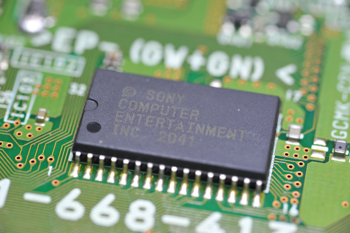
There are two variants of the PS1 mask ROM chip: a 32 pin variant and a 40 pin variant. The 40 pin variant is rare and only present in extremely early versions of the PS1 hardware.
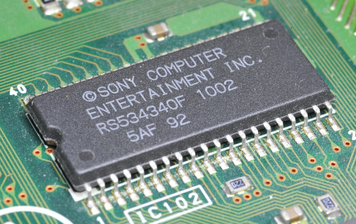
The much more common variant is the 32 pin mask ROM. This is likely the one in your PS1
Carrier boards exist for both mask ROM variants.
Flashing the New Chip
Flashing OpenBIOS to the new NOR flash will need to be done with a chip programmer, like the TL866. You cannot flash these chips with flashrom. Flashrom is used for programming serial chips. The TL866 and its variants are closed source, but they can be controlled with open source software. You will also need a TSOP adapter for the programmer.
The chip can be programmed with
minipro -p “MX29LV040C@TSOP32” -w /path/to/openbios.bin
You can optionally read the chip back a couple times to ensure it has been flashed properly. If the chip somehow got flashed incorrectly, desoldering it to re-flash will be difficult!
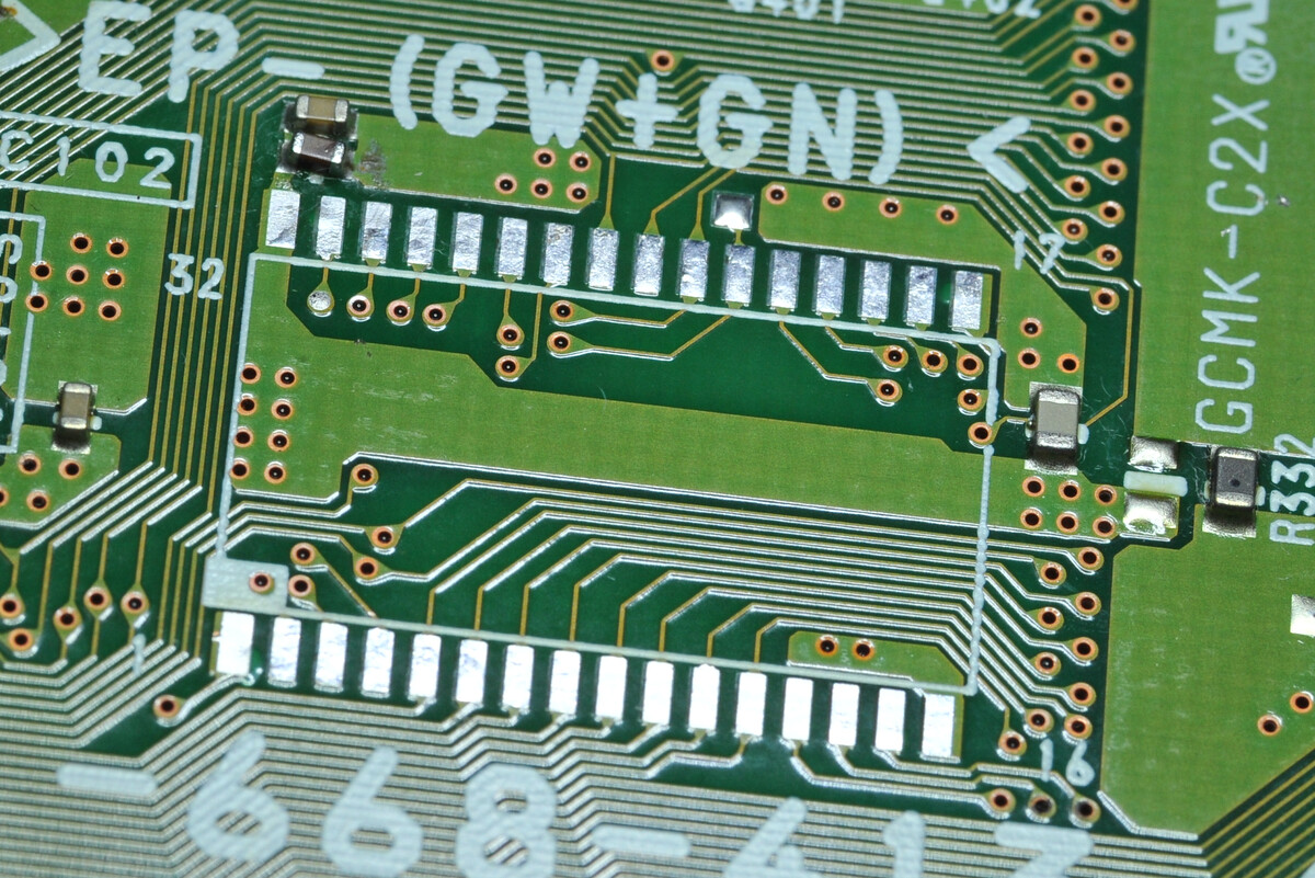
Removing the Existing Mask ROM
You can use something like a heat gun to remove the mask ROM from the PS1.
Make sure to thoroughly clean the area around the chip, and the chip itself and the pins on it, with 99.9% isopropyl alcohol. This is to remove any dirt and other contaminants that can get into the solder joints.
Before applying the hot air, you should flux the pins and re-flow them with quality 64/40 leaded solder. Make sure to thoroughly wet the joints with the solder when reflowing; this will bring down the melting point when using hot air, compared to joints of surrounding components, as all of the solder on this board will have aged a lot since manufacture, so oxides covering them would raise the melting point significantly.
If you do this, make sure to tack down any surrounding small components e.g. small resistors, capacitors, with kapton tape, so they don’t move or get blown away. You may also want to surround the chip with aluminium foil, to protect surrounding components.
Use a decent hot air rework station, and set the temperature to about 330C, or perhaps a bit higher, but 330C is likely OK. Remember, you’re not heating the chip. Go around the chip with the heat, making sure to heat the thick ground and voltage planes that connect it, which will soak up a lot of heat. You’re heating the pins on the chip. Go around the chip in quick succession, trying to keep the heat on all the pins as uniform as possible.
When the chip is ready to come off, you’ll know because you see the solder joints all melted. Nudging the chip a little bit will confirm if the joints are all fully melted, and then you can pull the chip off (a decent set of tweezers can be used for this).
Make sure to look at lots of videos online and maybe practise first on other scrap boards first, if you’ve never done this before. We don’t recommend any specific soldering kit.
As for soldering tip used when soldering: a T12-J02 or T12-K is sufficient, if you’re doing a drag soldering technique (pros only); otherwise, a T12-D08 will be acceptable also, if you feel the need to solder each individual joint.
Note that when purchasing those BIOS upgrade kits, the flash may not already be soldered onto the adapter board. If you’re not at all comfortable with precision soldering, you may want to ask the seller to ship it to you pre soldered, if you’re not flashing and soldering it yourself.
After pulling off the chip, clean up the remaining solder with solder braid and rubbing alcohol.
Soldering the Carrier Board
Solder the new carrier board to the PS1 motherboard.
Testing
All you should have to do is plug in your PS1, turn it on, and watch the screen. If you see a cube, it worked!
Game compatibility
The upstream maintains a compatibility list, here:
NOTE: Google Docs, but an option exists on there to export it for LibreOffice Calc. The list is provided as a spreadsheet.
Remarks about hardware
Modern NOR flash can be used. You specifically want a TSOP-32 SMD/SMT type device, one that operates at 3.3v (tolerance 2.7 to 3.6v), organised into 512KB blocks, for example 512KB x8 is a common part, for example SST39VF040.
Look here: https://oshpark.com/profiles/mi213
This person has designed PCBs that can be used to add a NOR flash, adapting to the pinout of the playstation BIOS. Some early launch model PlayStations used a 40-pin chip but most later ones soon after and to end of life were 32-pin. This page only sells adapters for use with 32-pin boards.
For most boards, the one you want is probably the PS1_Flash_Bios_(A) one.
We do not yet provide instructions for how to install this on real hardware, in the Libreboot project, but this can be done at a future date.
Other mods (hardware)
Modchip (mayumi v4) example
Click the photo for full size. It shows a Mayumi v4 modchip and Dual Frequency Oscillator mod installed (blue board is the modchip and the black board is the DFO mod). Mods installed by Leah Rowe, as a proof of concept:
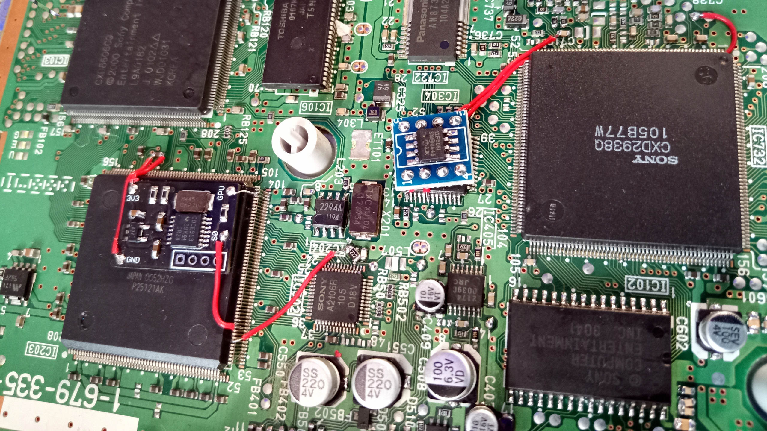
The modchip disables the copy protection and region restrictions. A modchip is still advised, even if using an Open BIOS. The Open BIOS could be modified to send commands that disable the wobble check, thus invalidating the need for a modchip, but even then there are still caveats. Please read:
https://psx-spx.consoledev.net/cdromdrive/#cdrom-secret-unlock-commands
The most technically correct solution, regardless of which BIOS you have, to also install the modchip and DFO board, as shown. More info is written about these in the next sections below:
Video timings
The Open BIOS will not implement any DRM, so it’s possible that you might boot out of region games. In an emulator, this is no problem, but it can prove difficult on hardware in a number of situations.
The purpose of these kinds of mods on hardware is typically that the user wants to remove all DRM. Well, there’s something many people overlook: video timings out-of-region are often wrong on these machines. The GPUs have two clock inputs (early launch models only have one clock input): one for PAL and one for NTSC. More info could be written here at a later date but these consoles typically don’t have a PAL GPU clock on NTSC consoles, and vice versa. You can correct this.
Look up the PS1 “dual frequency oscillator” mod. Without this mod, NTSC games will run slightly slower than they should and have the wrong colours, when booted on PAL consoles (and vice versa); RGB SCART can be used to mitigate the colour issue, but not the timing issue. The oscillator mod is the only solution for the timing issue.
The PAL GPU clock is roughly 53.2MHz, and divides by 12 to create the 4.43MHz PAL subcarrier/colorburst signal; this is needed in composite video for example.
The NTSC GPU clock is 53.693175MHz, and divides by 15 to create the 3.58MHz NTSC subcarrier/colorburst signal; ditto, this is used for NTSC composite video.
On a PAL playstation, Sony hardwired 53.2MHz to both inputs, and on NTSC, wired 53.69MHz to both inputs; that means on NTSC machines, PAL games will run with a 3.579545MHz colorburst signal, and on PAL consoles running NTSC games, the colorburst would be 3.55MHz. Some people suggest hardwiring a 4.43MHz clock to the video dac/buffer on PAL consoles, thus creating what is called a “PAL60” signal, but this is ill advised; ditto wiring 3.58MHz to it (NTSC50).
On most consoles except very early launch/debug models, and very late slim models, the PAL clock is pin 192 on the GPU and NTSC is pin 196 on the GPU. The Dual Frequency Oscillator mod uses a programmable oscillator and taps into the video mode signal off of the GPU to know whether PAL/NTSC is used; it switches the master clock hooked up to both inputs accordingly.
Another method is to cut the line going to the NTSC pin on a PAL console, and wire a 53.69MHz oscillator (at 3.3V, with the output through a 220Ohm resistor) directly to the pin; on an NTSC console, do the same but cut 192 and hook up 53.2MHz to it. The Dual Frequency Oscillator method is easier and therefore recommend, but you can do this other method, which I call DO (Dual Oscillator. Because it’s two oscillators!)
By fixing the timings in this way, your region-free console will also have correct timings, thus maximum game compatibility, and colours will always be correct no matter what video cable you’re using.
Modchips
If using hardware, you will probably still want a modchip. Many proprietary modchip firmwares exist, such as Old crow, MultiMode3 and Mayumi; these run on PIC chips e.g. PIC12C508A. A special OneChip firmware is often used on PAL PSOne Slims.
There is a free/opensource modchip type called PsNee, which is what Libreboot recommends: https://github.com/kalymos/PsNee
Unlike the other modchips, PsNee runs mostly on Arduino-type boards. You can find more info on its GitHub page.
Although not yet tested by Libreboot, it might be possible to have both the Sony BIOS and Open BIOS, by stacking them on top of each other, soldered pin for pin but leaving the OE/CS pins floating; then, wire up a switch that turns one chip or the other off, so that you can pick which BIOS you want at boot. This might be useful, in case you run into any compatibility issues with the Open BIOS.
A modchip is still desirable on OpenBIOS. The region lock and DRM is present in the disc mech firmware, and this DRM must be defeated with a modchip or by using the BIOS to send an unlock command to the disc mech on NTSC-US systems. OpenBIOS aims to be a fully compatible replacement for the stock BIOS, and thus it does not send the unlock command to the disc mech. The unlock command is not present in non NTSC-US systems like PAL or NTSC-J. Modchip installation on systems from these regions require the soldering of additional wires from the modchip to the BIOS chip so it can do some patching on the fly.
The PsNee modchip has been confirmed to work on real NTSC-US hardware with OpenBIOS. It is not known if the on the fly PsNee BIOS patching will be compatible with OpenBIOS.
More hardware testing is planned, but the Open BIOS works perfectly in emulators. Give it a try!
Boot games on SD cards
The PicoStation project provides free firmware for RP2040 devices, which you can solder into a modboard which then emulates the PS1 CD drive. It then lets you boot software (including many games) from an SD card instead of a CD, using disc image files, on a real playstation (the picostation replaces your CD drive).
PicoStation has been confirmed to work with OpenBIOS on NTSC-US systems. Since it replaces the disc mech entirely, it very effectively defeats its DRM. If you also replace the BIOS with OpenBIOS, the only nonfree software running on the PlayStation is in the SYSCON and any early bootrom code within the silicon itself. Perhaps someday we can get a free as in freedom replacement for the SYSCON firmware and achieve a more open gaming experience.
Not only is this useful in a development context, but it can also be used when your CD drive has worn out and no longer reads discs properly.
Final remarks
Combined with PsNee and PicoStation, the Open BIOS from PCSX-Redux team will turn your 90s PlayStation into a very hackable machine. There is also PSXSDK (which is also free/opensource) allowing for libre game development, also known (somewhat ambiguously) as “homebrew” development. The fact that these old consoles were designed to boot proprietary games is mere coincidence; they are simply computers, fully reprogrammable and as such, Libreboot is happy to provide this support, for the Sony PlayStation
Credit
Thanks go to the PCSX-Redux team for their excellent work reverse engineering the Sony PS1 BIOS.
The two photos shown are as follows:
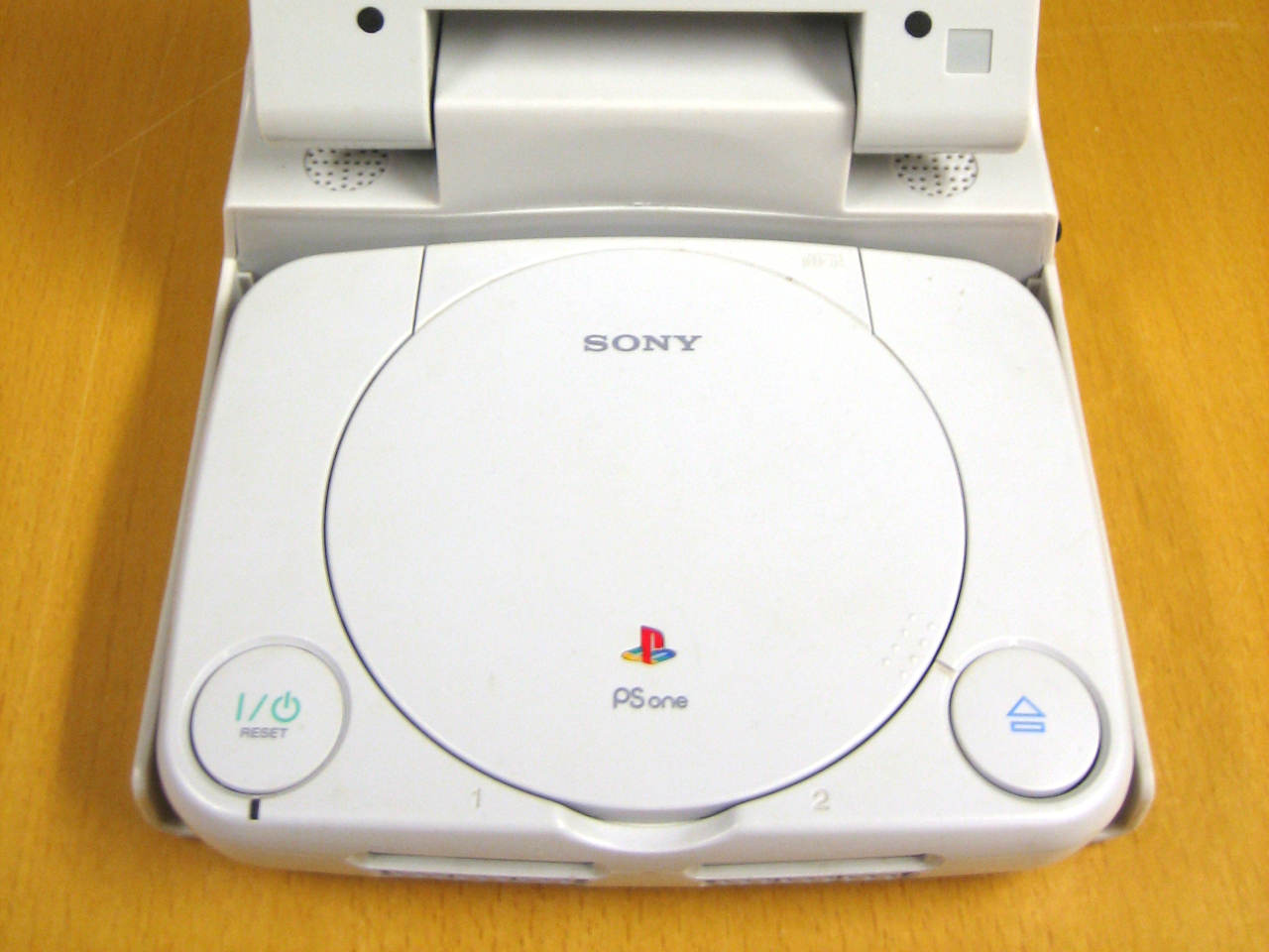
- PSOne Slim photo was taken from here (the one provided by Libreboot is scaled down and cropped, with color levels enhanced for better contrast): https://commons.wikimedia.org/wiki/File:PS_One_with_LCD.JPG - released under the terms of Creative Commons Attribution-Share Alike 3.0 Unported license
- The cube screenshot is of the PCSX-Redux Open BIOS in operation, on an emulator.
PlayStation, PS1, PSOne and other terms are the trademark of Sony Interactive Entertainment. Libreboot is in no way affiliated to Sony Interactive Entertainment; this page is not an endorsement of Sony Interactive Entertainment, nor do they endorse Libreboot.
PCSX-Redux developers are not affiliated with Libreboot in any way. We simply integrate their Open BIOS into Libreboot because their work is awesome.
The Canoeboot version of this page is: https://canoeboot.org/docs/install/playstation.html
Markdown file for this page: https://libreboot.org/docs/install/playstation.md
This HTML page was generated by the Libreboot Static Site Generator.