Install Libreboot ASUS Chromebook C201
Open source BIOS/UEFI firmware
This document will teach you how to install Libreboot, on your ASUS Chromebook C201 motherboard. Libreboot is a Free Software project that replaces proprietary BIOS/UEFI firmware.
WARNING: This board is known to have non-functioning video init at the time of writing, 19 February 2023. It is as yet unsolved.
See: https://notabug.org/libreboot/lbmk/issues/136
Introduction
This page contains information about assembly and disassembly, for flashing the ASUS Chromebook C201 externally. It will also link to internal flashing instructions, and information about U-Boot.
Flashrom
A special fork of flashrom, maintained by Google, is required for flashing. More information about this is present in the generic chromebook flashing instructions.
NOTE: Libreboot standardises on flashprog now, as of 27 January 2024, which is a fork of flashrom, but the chromium fork is another fork of flashrom, and you should use that on chromebooks.
Depthcharge payload (obsolete)
This board was also supported in Libreboot 20160907, with the Depthcharge payload. Support was dropped in later releases, and then re-added in the December 2022 release but with u-boot payload (not depthcharge).
Refer to older versions of this page, in lbwww.git, if you wish to see instructions pertaining to Depthcharge:
- https://notabug.org/libreboot/lbwww/src/4be2eed23e11b1071cd500a329abf654ab25f942/site/docs/install/c201.md
- https://notabug.org/libreboot/lbwww/src/4be2eed23e11b1071cd500a329abf654ab25f942/site/docs/hardware/c201.md
U-boot payload
U-Boot was ported to coreboot CrOS devices, courtesy of Alper Nebi Yasak (alpernebbi on Libreboot IRC).
Read the section pertaining to U-boot payload:
u-boot payload documentation for Libreboot
Internal flashing
External flashing is possible, but only necessary in the event of a brick. If you’re flashing good firmware, and the machine boots properly, you can do it in software, from the host CPU.
In the past, C201 was the only CrOS device so this page contained information about internal flashing. Libreboot now supports many more CrOS devices, so the information has moved.
See: chromebook flashing instructions
Write-protect screw
The chromebook flashing instructions, linked above, refer to a screw that can be turned, to disable flash protection. This is necessary, for internally flashing the C201. This section will tell you how to access that screw.
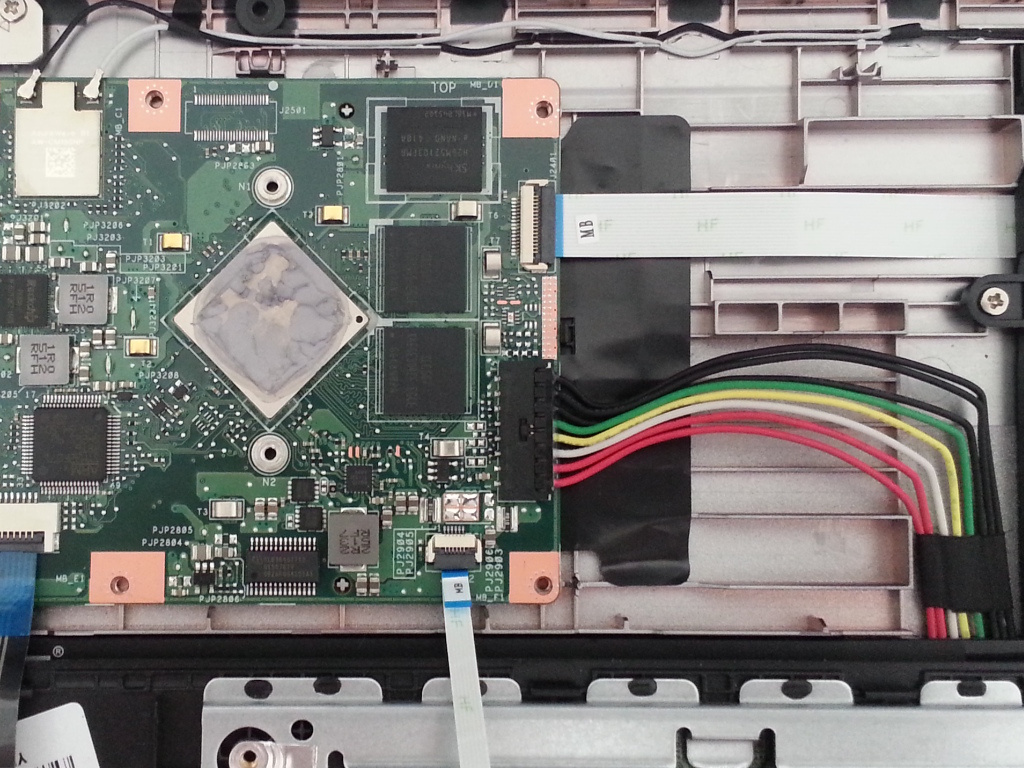
To access the screw, the device has to be opened. There are 8 screws to remove from the bottom of the device, as shown on the picture below. Two are hidden under the top pads. After removing the screws, the keyboard plastic part can be carefully detached from the rest. Beware: there are cables attached to it! It is advised to flip the keyboard plastic part over, as shown on the picture below. The write protect screw is located next to the SPI flash chip, circled in red in the picture below. It has to be removed. Refer to the following photos:


The write protect screw can be put back in place later, when the device is known to be in a working state.
External flashing
If the machine is no longer booting, due to bad firmware, you can unbrick it externally. Refer to external flash instructions.
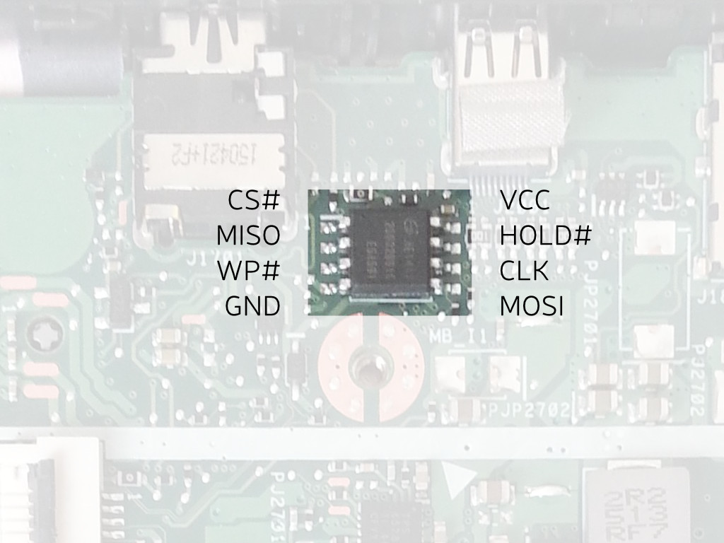
You do not need to correct the WP# pin because it is held high via pull-up resistor to 3.3v, when the write-protect screw is loosened (when tightened, the screw grounds this pin; the pull-up resistor is to prevent a dead short).
You must remove the battery, prior to flashing. The connector is shown in the 2nd photo, above (the big black connector, with the black, green, yellow, white and red wires going into it). Simply unplug that.
The Canoeboot version of this page is: https://canoeboot.org/docs/install/c201.html
Markdown file for this page: https://libreboot.org/docs/install/c201.md
This HTML page was generated by the Libreboot Static Site Generator.